USD Pipeline Breakdown
Introduction
Around 2023 I noticed that a lot of studios that my friends and I were working for or talking to had started to move away from the variety of scene compiling programs they had traditionally used (Maya, Katana, Gaffer, and Clarisse) and toward a Universal Scene Discription (USD) based pipeline in Houdini Solaris. Since i already had a background as a Houdini artist, I decided to get ahead of the curve and learn as much as possible about Solaris’ implementation of USD.
To do this, I decided to attempt creating a few fully CG shots while restricting myself to building and storing everything within the USD package. My goal was to explore as many points of the CG pipeline as possible, experiencing firsthand both the advantages and limitations of USD and gaining a deeper understanding of how it could shape visual effects workflows in the future.
Here are some of the most useful refrences i used for this project if you want to read more:
https://www.sidefx.com/tutorials/usd-asset-building-with-solaris/
https://www.sidefx.com/tutorials/usd-authoring-with-solaris/
Process
Kitbash Preparation
To start, I chose to use some Kitbash3D collections I had purchased. The main challenge was that Kitbash does not provide USD downloads so I needed to convert these models into USD files.
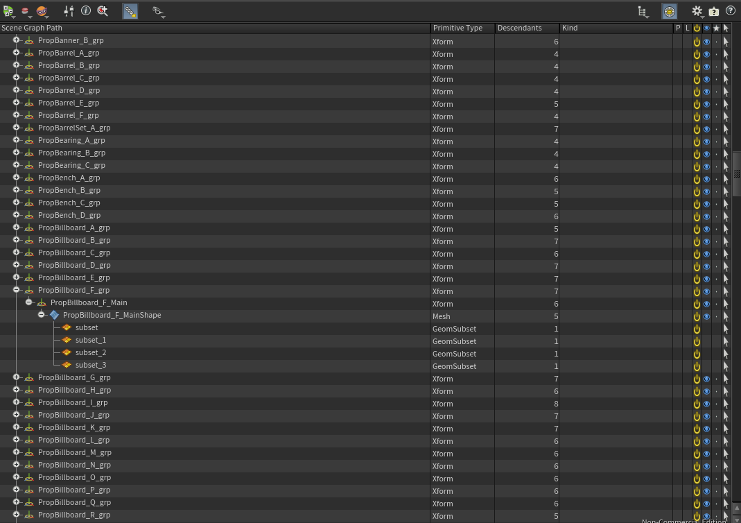
Because I knew I would need to modify and add models, and because I preferred Kitbash’s Maya implementation over Houdini’s, I began in Maya. Using the Outliner and Python scripts, I organized and renamed both models and materials to facilitate import into Houdini. I simplified names by removing unnecessary collection tags and adjusted texture paths so they were relative to the project file in a format Houdini could read. After this cleanup, I exported the entire package as a single USD file and moved it into Houdini.
Collections Setup
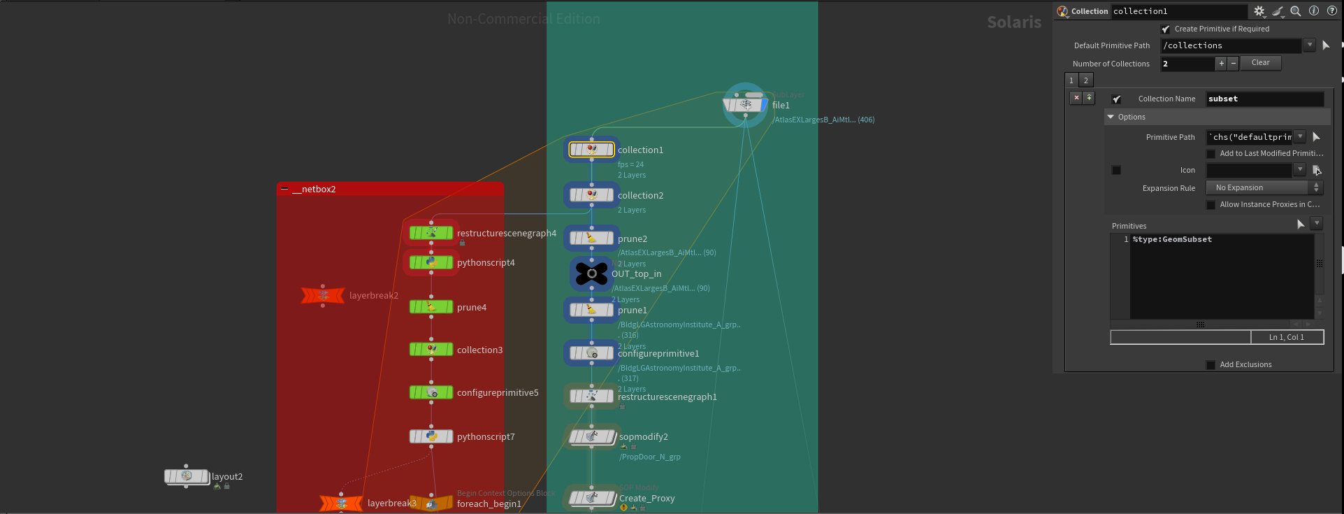
After importing the prepared USD as a sublayer, I created collections for use later in the pipeline:
Material primitives
Mesh primitives
Subsets containing material assignments
Top-level transforms for each object
I then split the workflow into two paths: one for geometry and one for materials.
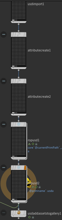
Geometry
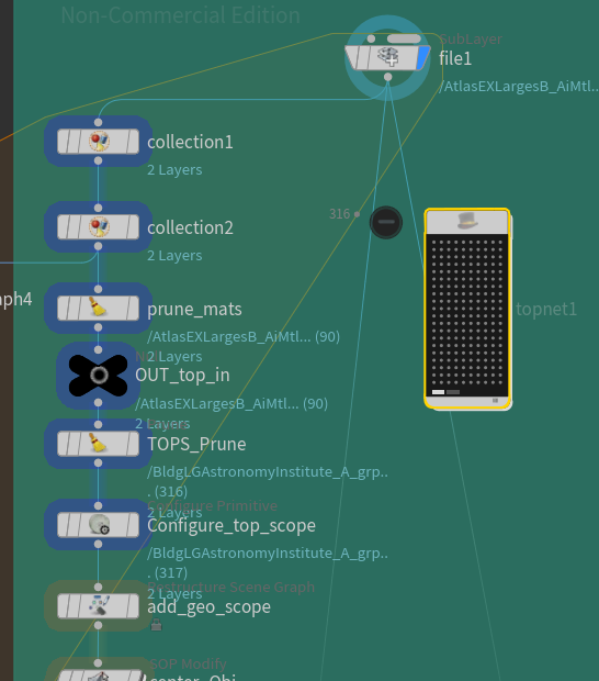
For geometry, I used a TOPs network to process each object individually by iterating over the objects contained int the ‘top level transform’ collection. This allowed me to write out a series of USD files for each object with a single operation, which were then packed into the final output of this stage.
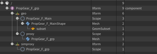
After isolating each object with a TOPs attribute, I added a “geo” scope to hold both render and proxy geometry, keeping them separate from the materials. Since Kitbash assets arrive in a displayable spread-out form, I repositioned each object to the center using a SOP Modify.
Next, I used a SOP Create node to generate two proxy types: a display proxy and a simulation proxy. For the display proxy, I kept poly counts low while maintaining recognizable shapes by creating primitive boxes around each connected piece of geometry. For the simulation proxy, I preserved more of the original shape so that Solaris’ physics tools would function accurately, using PolyReduce to simplify geometry while retaining the silhouette. These proxies worked well for nearly all assets, enabling smooth integration with Solaris physics.
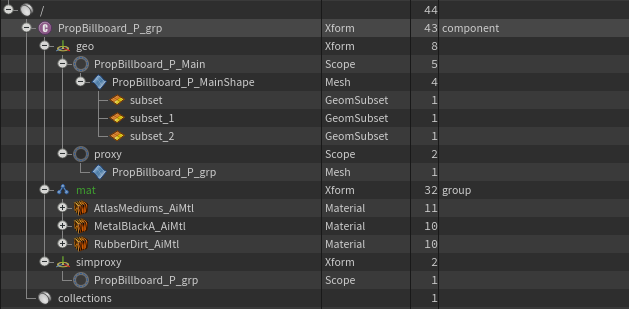
After geometry processing, I switched the top-level node to a component. I repathed the material bindings to exist within the component and created an attribute on the subsets to assist with rebinding materials when referenced back into the component. At this point, the geometry portion was complete. I created a layer break, wrote the geometry USD to its on-disk location, and moved on to material preparation.
Materials
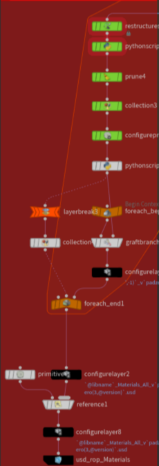
To create the material USDs, I moved all materials under a “Mat” sub-component. I then used a Python script, modified from an Arvid Schneider tutorial, to generate USD Preview materials for each material in the library. The script identified base color and roughness maps and plugged them into the USD Preview shader, allowing visualization in Houdini’s viewport without rendering.
Each material was then configured in its own layer, enabling modular files that could be referenced by objects as needed. I referenced these individual material USDs into a larger library and exported the combined result.
Finally, I referenced the materials back into the assets. Using the attribute I created earlier, I located the correct materials in the library and referenced them into the asset. Since the subsets had moved within the component, they required reassignment through an Assign Material node. Once completed, the materials were fully integrated.
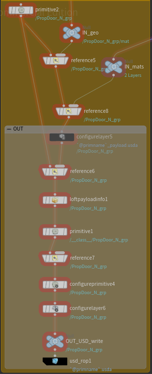
Payloading and Technical Preparation
With geometry and materials ready, the asset was technically usable, but I implemented additional optimizations.
I created a payload file by referencing both the geometry USD and the asset-specific material USD as subcomponents in a new layer. This structure allowed for a lightweight top-level USD that deferred loading the heavy data until needed.
To make this useful, I configured the top-level USD to ensure the file had the proper behavior. Lofting the payload provided access to useful information, like bounding boxes, without loading the entire file.
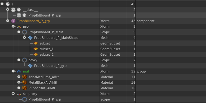
I also set up a class primitive for the asset. While not strictly necessary, this allows for non-destructive edits later, particularly for instanced objects. Finally, I added metadata to make the asset identifiable and compatible across programs. At this stage, the asset was ready for export.
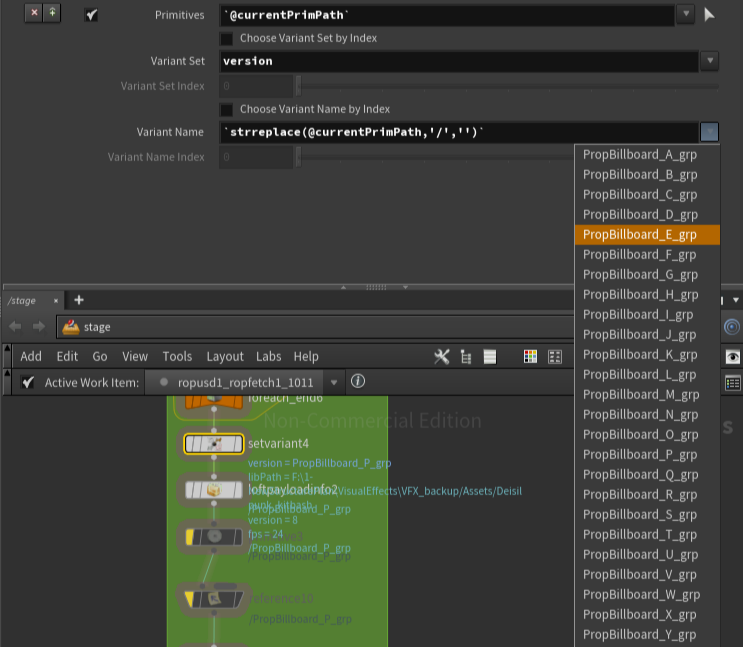
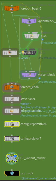
Variants
For the final step, implemented USD’s variant system to switch easily between similar Kitbash assets.
To accomplish this, I processed all assets without variants, writing out what I called a ‘ core’ USD files. Then, in my TOPs network, I processed a second branch to generate top-level USDs containing variants. By analyzing object names, I identified assets with the same base name but different variant letters, referenced their core files, and created variants in the top level file for each object. Metadata was then updated before final export.
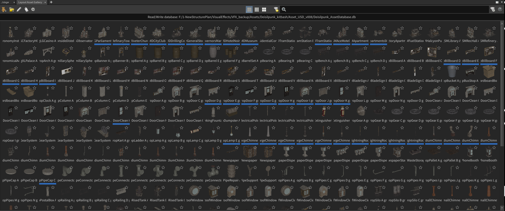
Asset Gallery and Database File
I packed all top-level USD files into an Asset Gallery database. This allows visual selection of assets for layout and environment work using Solaris tools.
The asset pipeline was now complete. Kitbash assets could be used efficiently with proxies and payloads, and variants. This workflow also allowed for the addition of new models from Maya that passed through the same Houdini process and appended to the database, ready for immediate use.
Project
Layout
I returned to Maya to set up cameras and perform a basic layout. Using the Dieselpunk asset pack, I created planes for roads and cubes to block out building locations. Once I finalized camera angles, I saved the camera and blockout geometry as USD files and imported them into Houdini.
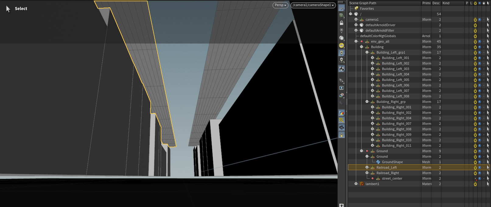
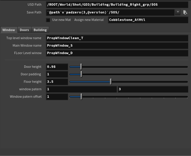
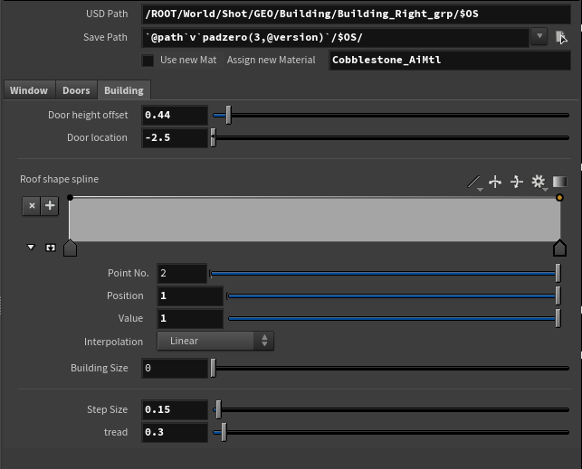
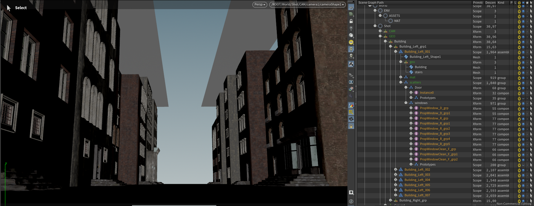
Building Builder HDA
I created a procedural building HDA to generate building assembly for each blockout building placed in the layout scene, including windows, doors, roofs, and textures from the asset database. I used scatter USD files for asset groups and referenced them into a USD containing the final building assembly.
This workflow kept USD files manageable while allowing adjustments to individual components. The HDA replaced blockout geometry with references to the final assembly USD, forming the base scene. Buildings could then be instanced along a line with variation to extend the alleyway.
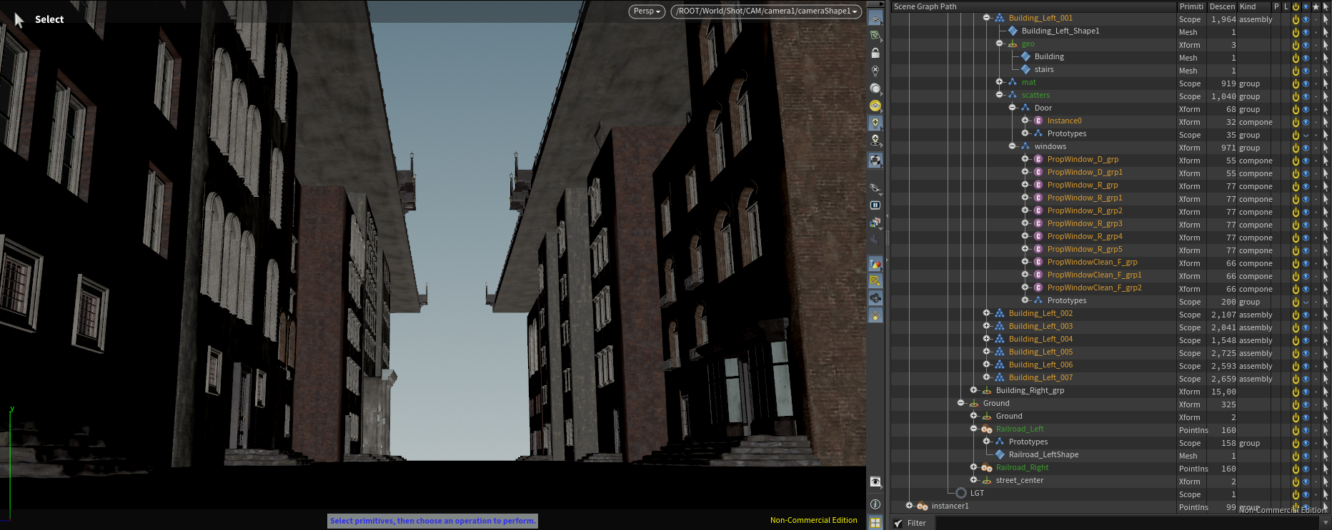
Scattering
Roads were straightforward to place along the scene layout. The main complexity involved instancing a train station at a specified point, achieved using a path attribute.
I also created piping along the road undersides using small interchangeable sections that aligned with the roads. These were scattered to create visual complexity without the manual work of placing every pipe.
Lower Roads
For the lower alleyway, I procedurally generated bricks with multiple levels of detail, then populated the area with infrastructure, grass, and trash using scatter and instance workflows. This created a dense, lived-in environment.
Upper Roads
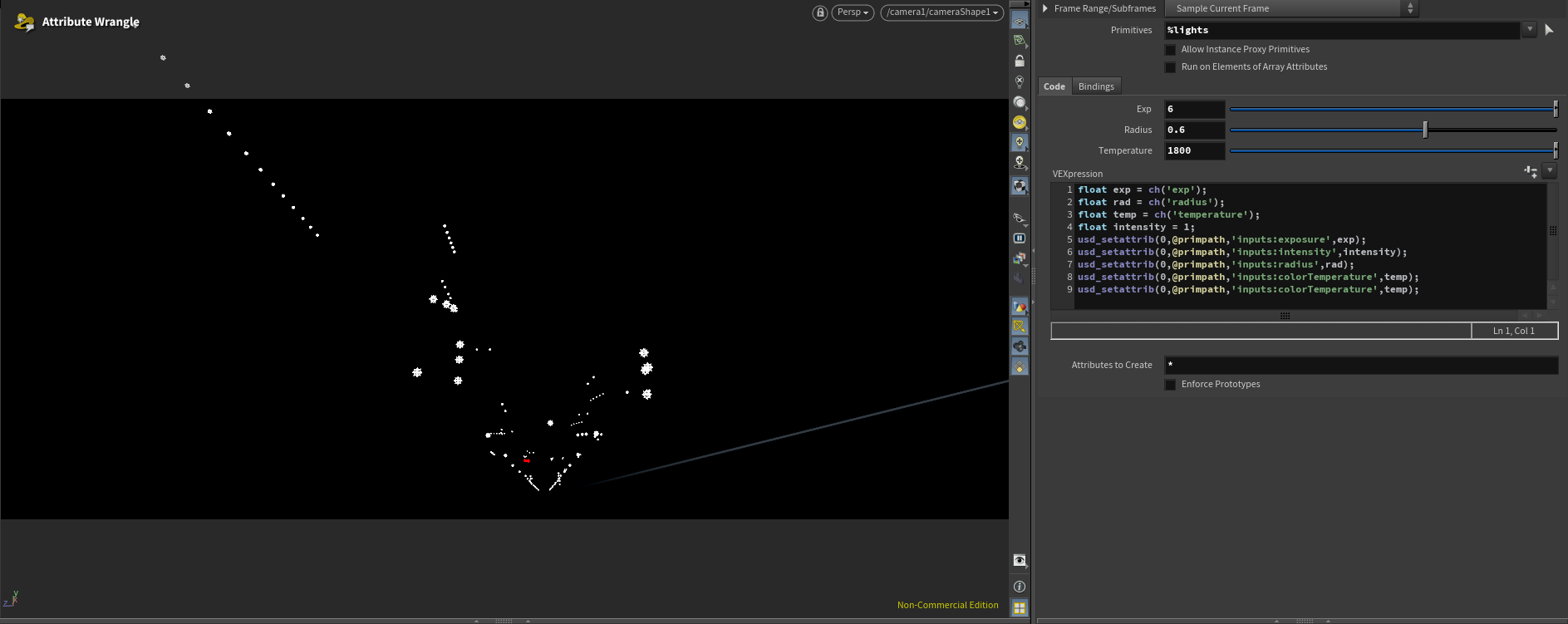
Lightrigs
Lightrigs were built using several techniques. I began with basic exterior lights for the sky and sun to establish a baseline. Then I created environment lights from lamps and emissive objects.
Assets containing lamps were modified with added primitives storing light location and rotation information. I extracted these points in a separate file to scatter lights efficiently. Lights were organized into assembly by the source asset name, providing maximum control with minimal manual effort.
I also modified some windows by replacing glass with emissive material to enhance the scene’s realism.
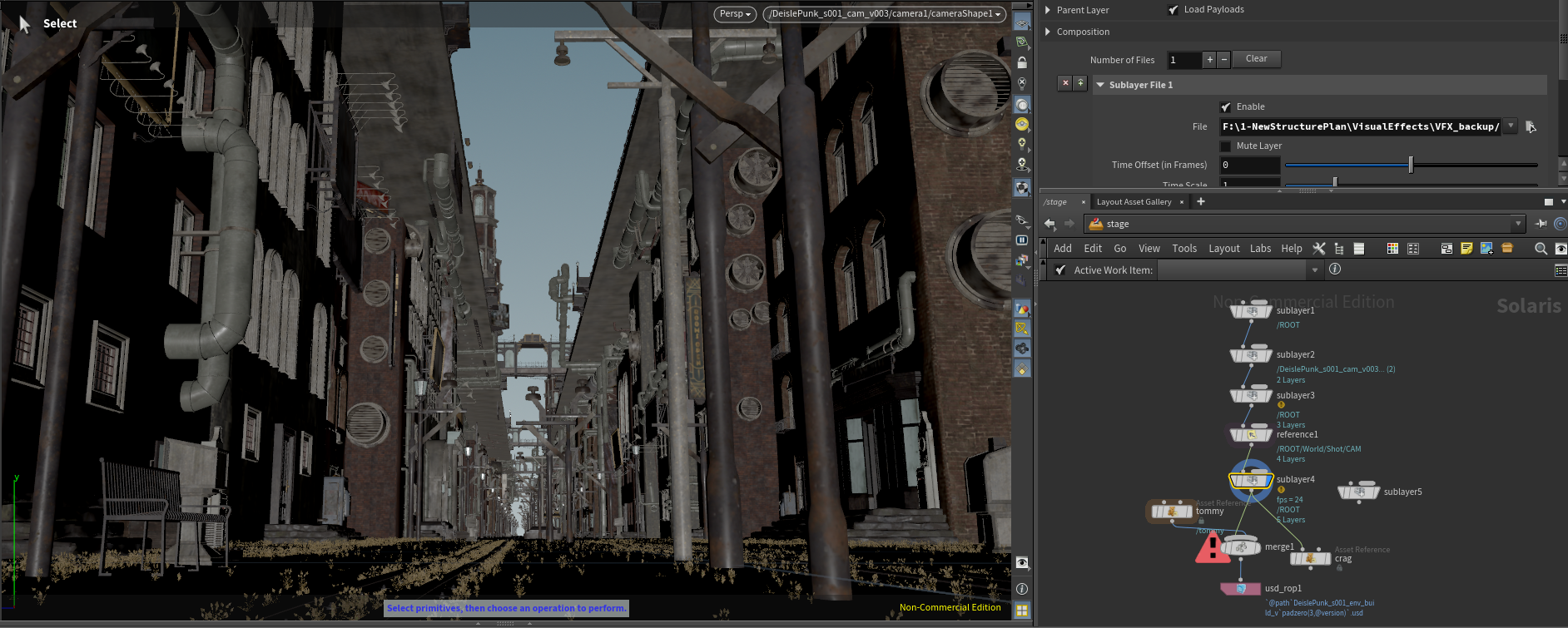
Finalization
I referenced all saved USD files for each group and constructed the final scene. Additional elements such as fog and train cars were added. With geometry, materials, and lights in place, I configured render settings, AOVs, and prepared the scene for final render.
To be Continued
There is still room for improvement. I plan to refine this workflow for other shots. I am still unsatisfied with the composition and aim to create more engaging setups in the future. Additionally while the Building generator worked well for the background building I don't believe they hold up in the foreground. I modeled some buildings manually but have not had the chance to texture or replace them in the scene yet.
A key limitation is updating asset versions. Currently, I can override or rewrite top assembly files, but this is not optimal. I am developing a Python tool to track, modify, and update files more efficiently, which should streamline the process.
I also faced limitations with USD support in mainstream texturing software. For example, upgrading foreground Kitbash assets was impractical due to the work required. In Mari, USD tools are only available as a paid plugin, restricting learning access for non-commercial users. I hope future updates remove these barriers for educational purposes.
I am looking for ward to updating this page in the future when i have the time as I enjoyed woking on this project and would like to see it in a final presentable state.